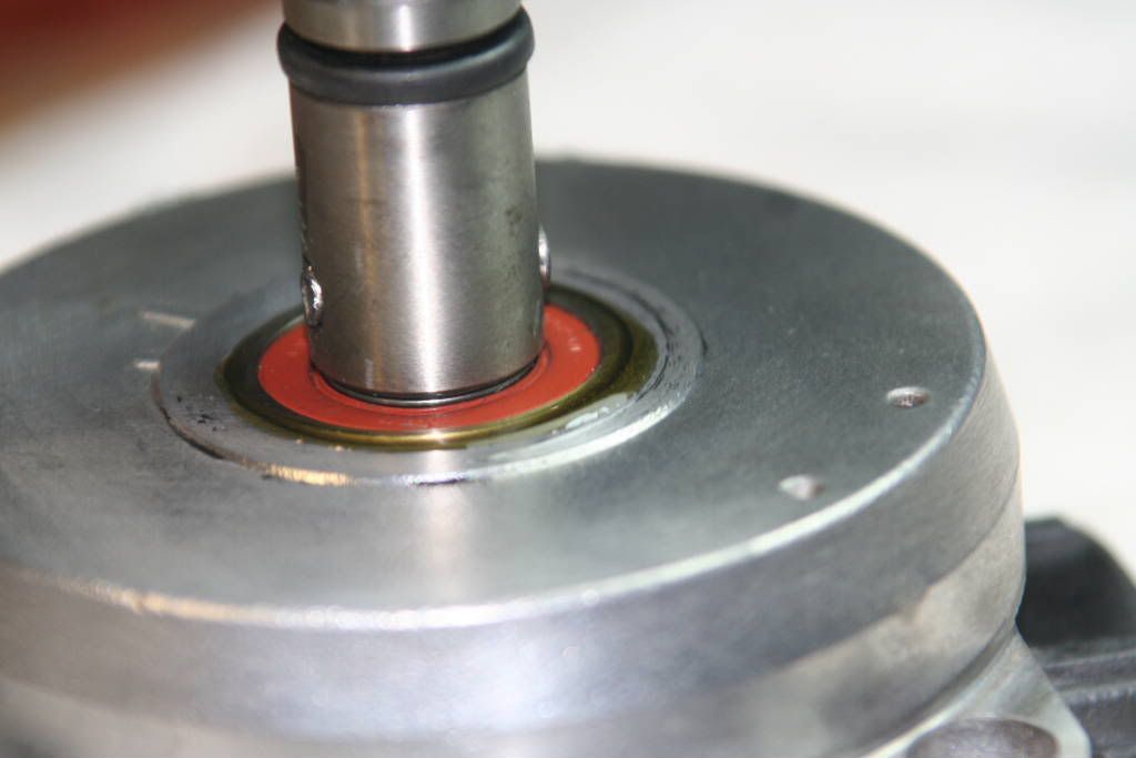
Step one: Removing housing screws
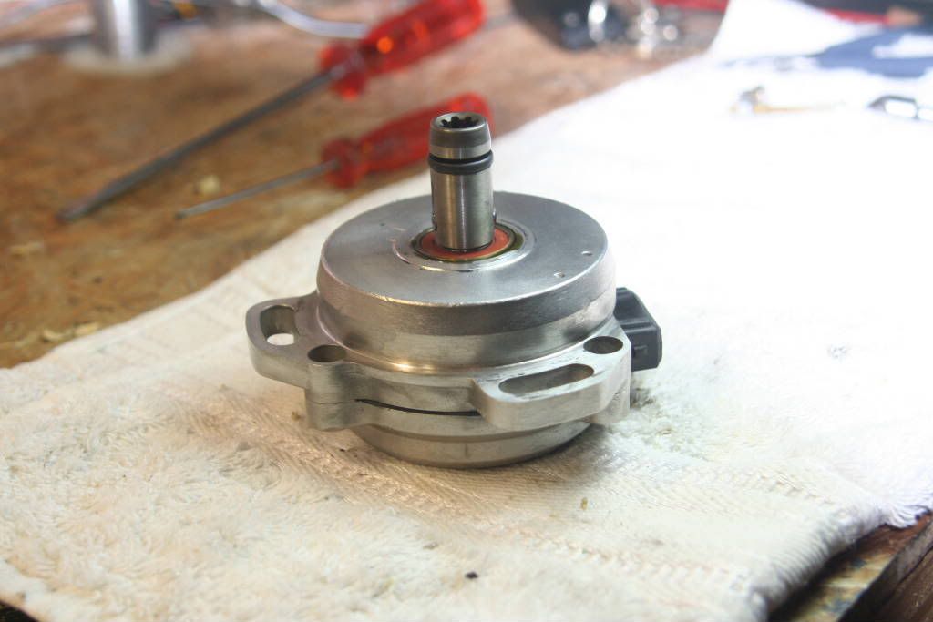
Open your CAS. Unfortunately I do not have a picture of this, but you need to remove the three sunken screws in the rear housing of the CAS. The rear housing is the one that accommodates the half shaft that links with the exhaust cam’s half shaft. Although it will be difficult to pry the two housings apart, they will let go eventually, but be careful not to damage the housings to much.
You may also have to remove the metal plate that covers the black plastic plug that sticks out of the CAS. This requires you to remove two more screws.
Step two: Separating housings
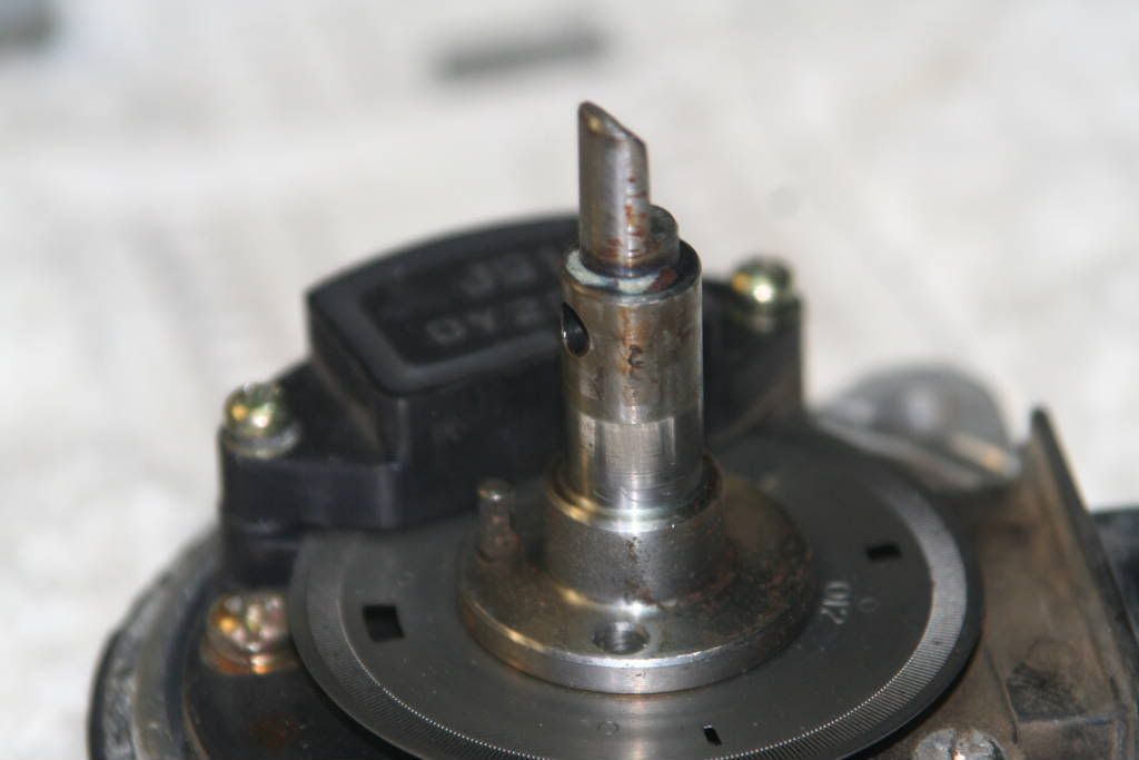
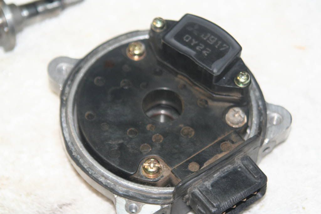
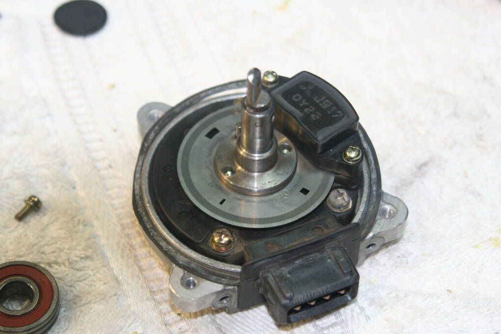
Your CAS housings should now be separated, and one piece should look like this.
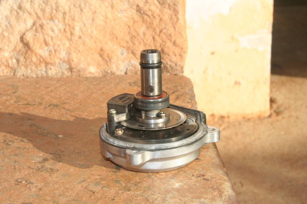
You can clearly see the different parts of the CAS.
1 The splined shaft that is fitted over the half shaft and held in place with a pin. This shaft also should have a rubber O-ring near the top of it.
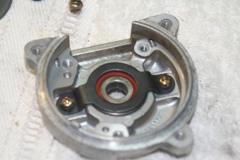
2 The smaller bearing, sized 6000.
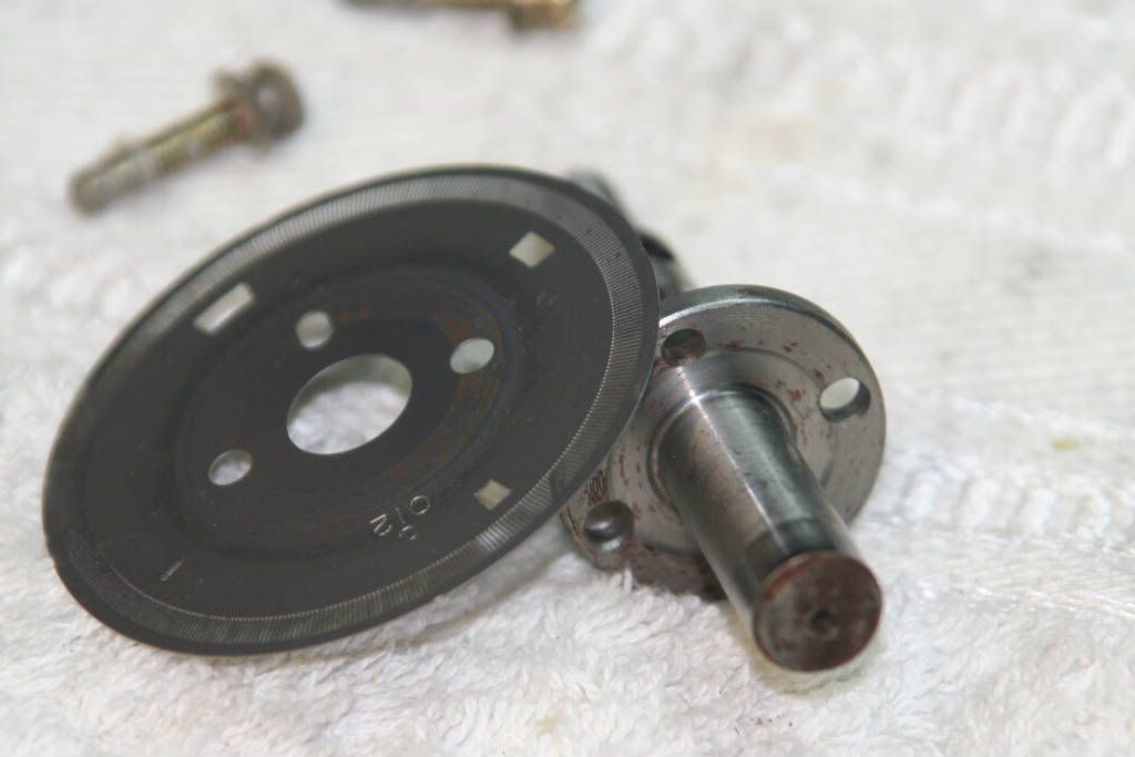
3 The chopper disc that is attached to the shaft.
4 The electronics component that covers the top and bottom of the chopper disc.
5 The seal around the edge of the housing that prevents most water and dirt from finding a way in. This seal is not water or dirt tight however, and it might be dirty in there!
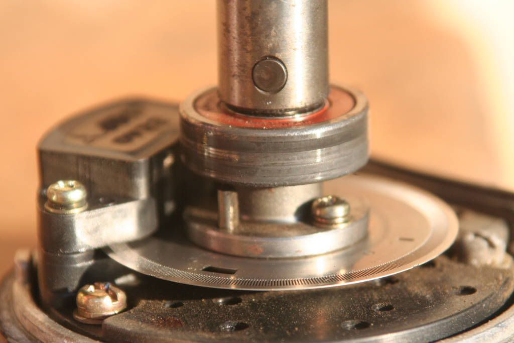
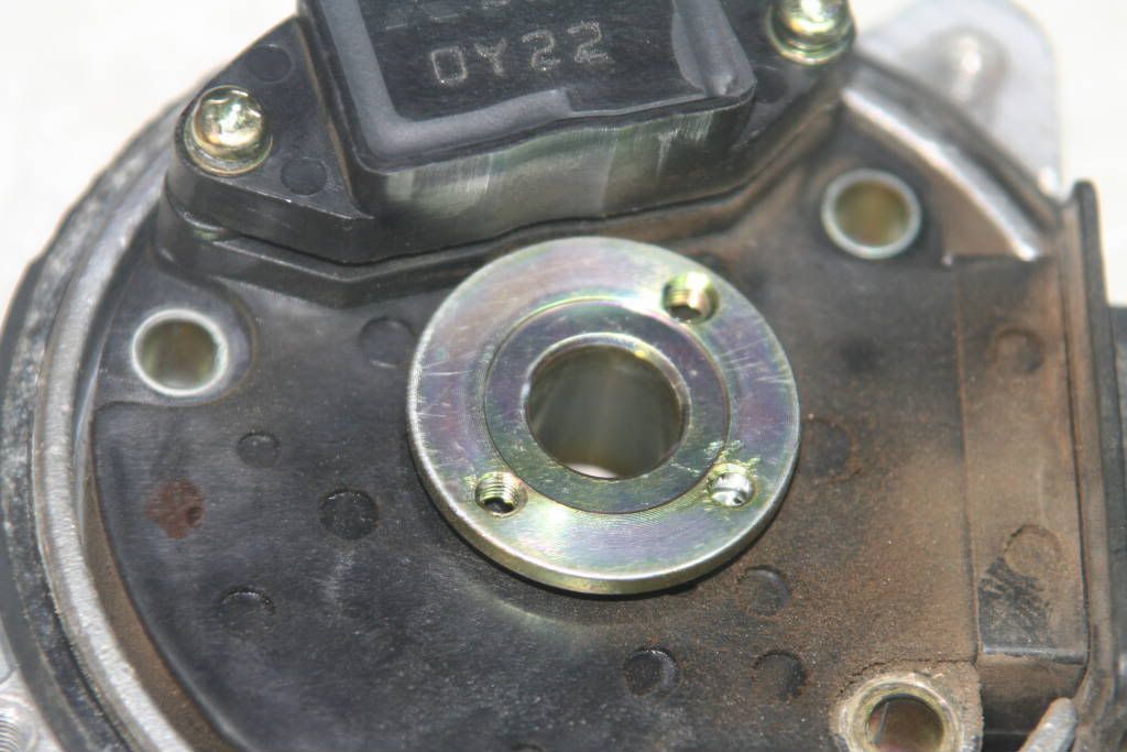
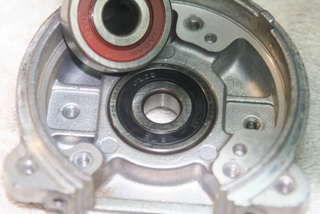
From this picture you can clearly see the scuff marks on the outer edge of the bearing. It is my assumption that the bearing was spinning inside the CAS housing. This is not supposed to happen, and may cause electrical interference, which may cause intermittent problems like I experienced.
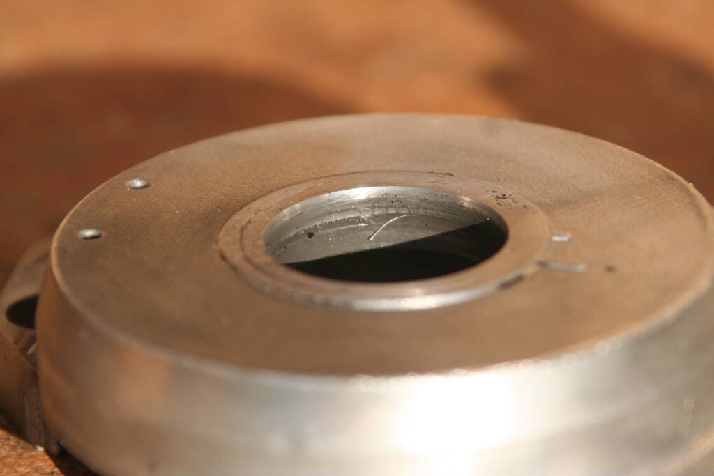
This picture of the housing that the small bearing was in also clearly shows evidence of metal rubbing on metal. In fact, the dirt on the inside of the housing was exactly like that produced when 1200 grit water paper, and water, is used to sandpaper aluminium.
Step three: A quick once over
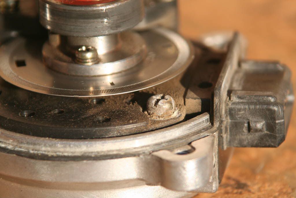
I added this step in so that people can quickly check out the state of their CAS’s. you should be looking for worn bearings, loose screws, a bent or damaged chopper wheel, dirt and dust build up, broken seals, etc. Basically check that everything is ok.
You can also see how much dust and dirt has built up inside my CAS. That just cannot be a good thing so I figured its best to clean it while I was busy taking it apart. Also, my bearings were badly worn, and I could tell because they would spin freely. The rest of the things mentioned though, were OK.
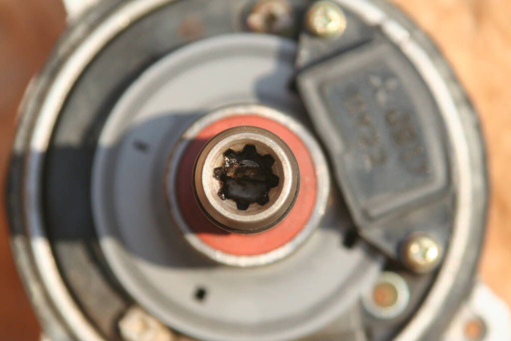
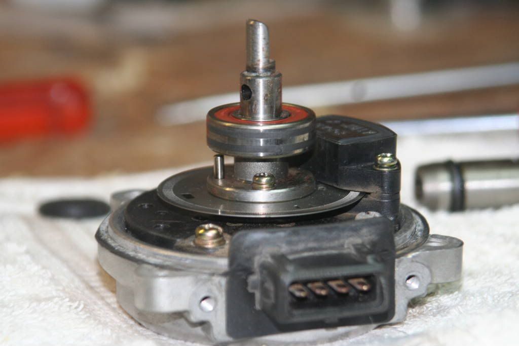
Another important check is on the condition of the splines and the locating pin in the CAS shaft. From this picture you can see that on this particular CAS they are fine. Just a bit of dirty grease in there, but that will be cleaned and replaced once the splined shaft is removed.
Step four: removing the splined shaft
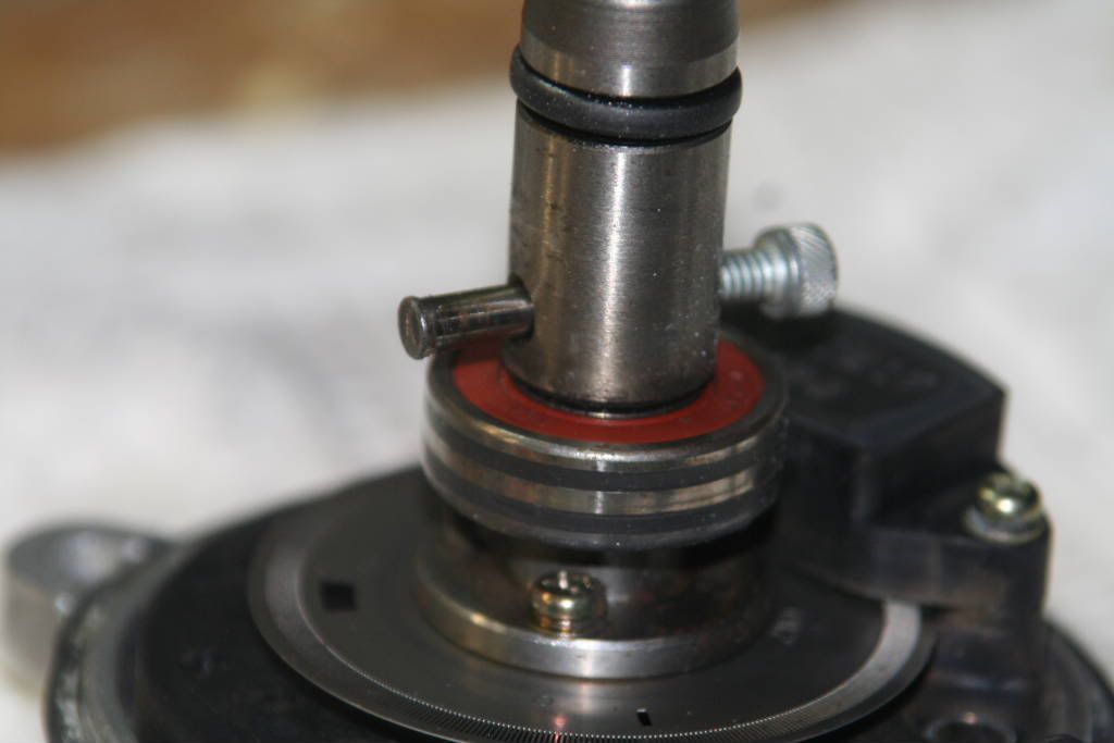
Remove the retaining pin that keeps the splined shaft in place. If you want to replace the bearing, this has to be done. But remember that one of the pins ends is flared slightly, so it can only be removed from one side. A press would be the ideal tool to do this step, but if that is not handy, there is a trick with a vice and a socket that works.
My CAS retaining pin was a real bastard to remove, so expect it to resist. You may think it’s not possible, but it is.
Once the pin has been removed the splined shaft will slide off. Be careful though, there is a rubber O-ring fitted between the splined shaft and the inner shaft. It can get damaged when you remove the splined shaft.
Step five: removing the smaller bearing
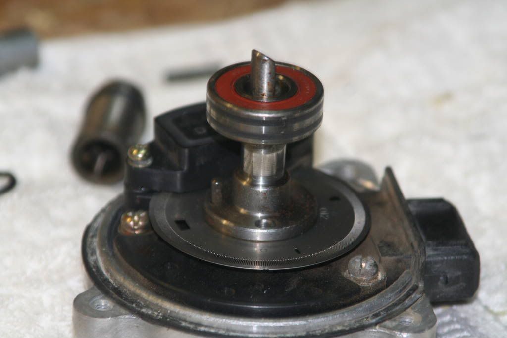
I used a bearing puller to remove this bearing. I placed the center of the puller at the center of the half shaft. I then place the 3 arms of the puller around the bottom of the bearing and gave it a few turns, and it worked itself loose.
Once the bearing was out of the way, I also removed the screws that held the chopper place in place.
some more in the next post!
