Page 2 of 5
Posted: Mon Jun 11, 2007 4:11 pm
by Gary57
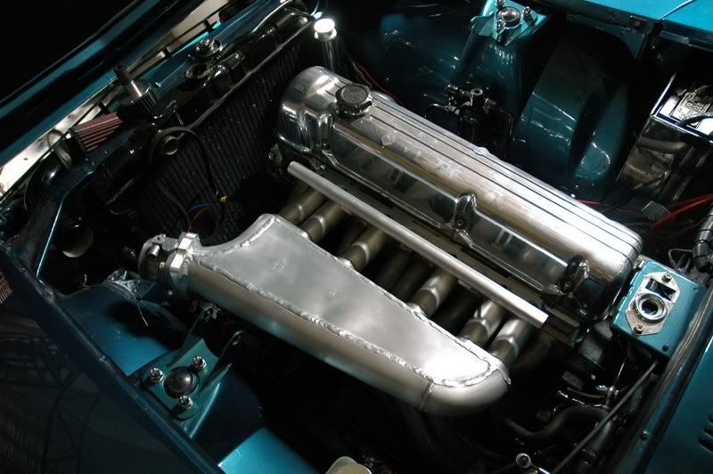
The less of an angle the air flow through the better. A sudden reduction in effective diameter yields a far greater head lost than a bend of any kind. The plumen is a reservior yes, but can also aid in cyclinder distribution.
If you angle them all to the throttle body you will get shrouding unless you have a huge plenum
Excuse my ignorance but what is shrouding and how does a larger plumen help this??
Posted: Mon Jun 11, 2007 4:12 pm
by Phinx
Sorry But I have to post this.. .
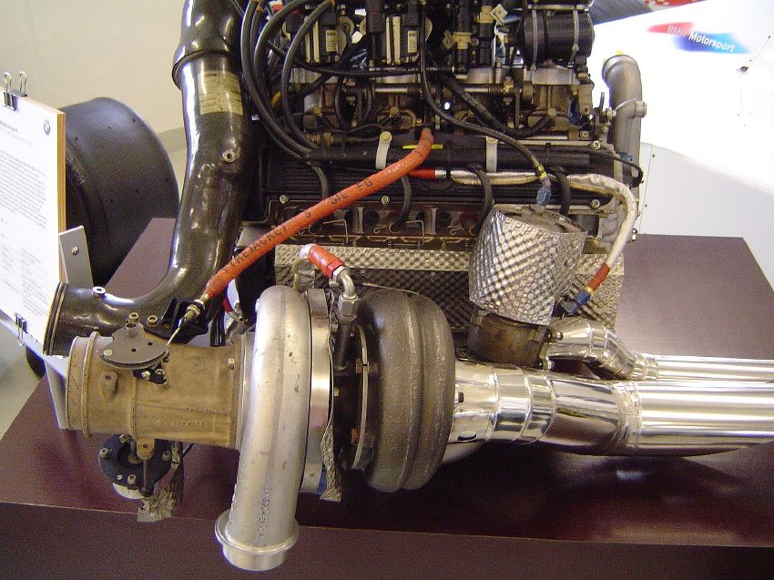
Check the intake, The Old F1 turbo era

Posted: Mon Jun 11, 2007 4:16 pm
by Gary57
Oh WOW what an engine, those were 1500cc hey?? That size turbo for 750cc each

.
Did you notice the position and angle of the external watsegate, not sure if it was because of space constrants but that goes against everything I have read. I thought the angle going to the external wastegate should aid in the flow out of the manifold, ie equal angle between the turbo and wastegate??
Posted: Mon Jun 11, 2007 4:20 pm
by Phinx
Do you mean an Intake like this gary?

Posted: Mon Jun 11, 2007 4:24 pm
by Gary57
Yes that kind of thing. I can see the runners so cant comment on it but thats what I would be looking at. I would like to see a smooth progressive flow into the runners rather than sharp 90 degree turns.
Posted: Mon Jun 11, 2007 4:34 pm
by johansx
Posted: Mon Jun 11, 2007 4:34 pm
by Vlade
The Calibrator wrote:Well on all the import motors I the first intake chamber are always the dirtiest on mine and Ero's I had to manually clean them...
Dirty intake runner normally means
Little airflow (leass than the others) Dirt settles where the air speed is lowest.
Reversion ie intake valves dont seal properly or cam overlap excessive at low rpm.
Engine breather directed to or near the runner in question.
in any engine the cleanest intake runner assuming a good condition engine will have the highest air flow.
Sorry

Cool once again I learned something

But ok then the last runner gets the most air in our plunems
Posted: Mon Jun 11, 2007 5:00 pm
by Phinx
Damn Check where the throttle control is on the F1 turbo's
There is no need for a BOV, thats old school with these guys, On qualifying the ran a 5.2 bar boost presure and used water sprayers on the intercoolers.
They used about 3 liters a lap of water and made on average 1300 HP they also had anti-lag systems
They have forgotten what we want to learn
Posted: Mon Jun 11, 2007 7:11 pm
by The Calibrator
Excuse my ignorance but what is shrouding and how does a larger plumen help this??
You have completely misunderstood everything I have said. If you angle the runners and have venturis will one side of the venturi not be closer to a wall than the rest of it? Hence it will be shrouded, the only way around this is to build a huge plenum so the venturis can be far from the walls. This brings other problems as there is an optimum size for plenum chambers.
Show me an example of any modern intake where the venturis are aimed at the TB.
Ever single manifold pictured has a plenum with runners at 90 deg to the airflow therefore I must assume that everybody else out there has the same stupid idea.
I am done trying to explain this maybe you should build a manifold that will make 25kw by itself. I will just keep building mine in the same kak way untill someone can prove to me there is a better way in the space available.
By the way the butterfly on the turbo above is not a throttle. Renault did that to aid anti lag they shut that on overun so the turbo is in a vacuum and can thus maintain more speed.
Posted: Mon Jun 11, 2007 7:12 pm
by Gary57
That is the first time I have seen that, I wonder what the benefits and disadvantages would be?? I know throttle response would suck, but then on a system that runs antilag it wouldn't be that bad.
Posted: Mon Jun 11, 2007 7:18 pm
by The Calibrator
That is the first time I have seen that, I wonder what the benefits and disadvantages would be?? I know throttle response would suck, but then on a system that runs antilag it wouldn't be that bad.
By the way the butterfly on the turbo above is not a throttle. Renault did that to aid anti lag they shut that on overun so the turbo is in a vacuum and can thus maintain more speed.
Posted: Mon Jun 11, 2007 7:26 pm
by Gary57
Show me an example of any modern intake where the venturis are aimed at the TB.
Show me one intake that doesnt have mass production or cost in mind?! I still dont think you know what I mean, umm, kinda like a turbo manifold but with a plumen in the place of the turbo and shorter runners (this is a very vague discription). Ill try get time to draw a rough sketch and post it.
Posted: Mon Jun 11, 2007 8:19 pm
by The Calibrator
I have a pretty good idea of what u mean. You want the entance of the runners pointing at the throttle body.
All the manifolds on the F1 engines above use exactly the same technology I am using just with more design work and carbon fibre.
Surely they dont have costs in mind?
Anyway I am pretty happy with what I am building why dont you build 2 one the conventional way and one your way. Test them properly and then we will know what works better in that particular application.
Posted: Mon Jun 11, 2007 10:00 pm
by Phinx
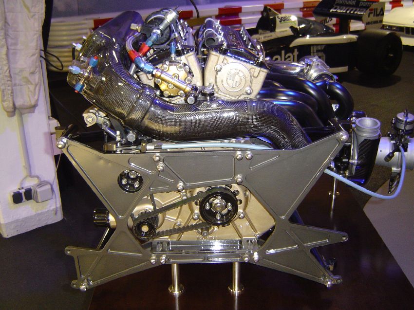
Sorry Calibrator, But the above picture is a BMW F1 Turbo motor.
But It seems are right there are ITB on this set-up and A "pop off valve"
Here is a Picture On the intake manifold on the same motor
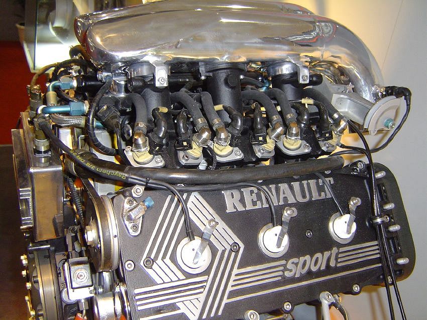
Here's a Picture of the Renault system, From the information I have the F1 teams use a special "injector" as an anti-lag system on some of there motors.
The Renault used intake throttles
Posted: Tue Jun 12, 2007 7:07 am
by The Calibrator
Renault's engine designer in the F1 era invented the system of a TB on the turbo. It is linked to the accell linkage and closes when the throttle is closed allowing the turbo to spin in a vacuum. Once they had materials to cope with the extreme heat generated they did run a bypass valve which allowed air into the exh housing and injected fuel into it to keep the boost up.
They could generate full boost on a closed throttle and I am pretty sure the other guys caught on quickly.
On another note the fuel they used was 87% toluoene and Shell developed a technique to impact water into the fuel as a anti detonation measure. This was done in such a way that water molecules were surrounded with fuel molecules. When the water was heated it burst the "package " helping with atomization.
this allowed the Frerraris to make huge power.
That BMW motor was a production 318 cast iron block with a dry deck system so water couldnt get into the combustion chambers when the head gasket blew. Note I said when not if they even had small grooves in the block to channel the gasses away from the other combustion chambers so that the motor would finish the race.
Its pretty fascinating stuff.