Article #2: CAS bearing replacement.

How-to's, project cars, and various other articles posted by club members

Moderators: P3g4sus, Daniel, rat, Draco, Riekert

Post Reply
veecee
AGENT SX!
Posts: 7353
Joined: Wed Nov 08, 2006 3:49 pm

Article #2: CAS bearing replacement.

Post by veecee »

The illustrated guide to changing bearings on your CA18DET Crank Angle Sensor (CAS).

Step one: Removing housing screws

Image

Open your CAS. Unfortunately I do not have a picture of this, but you need to remove the three sunken screws in the rear housing of the CAS. The rear housing is the one that accommodates the half shaft that links with the exhaust cam’s half shaft. Although it will be difficult to pry the two housings apart, they will let go eventually, but be careful not to damage the housings to much.

You may also have to remove the metal plate that covers the black plastic plug that sticks out of the CAS. This requires you to remove two more screws.

Step two: Separating housings

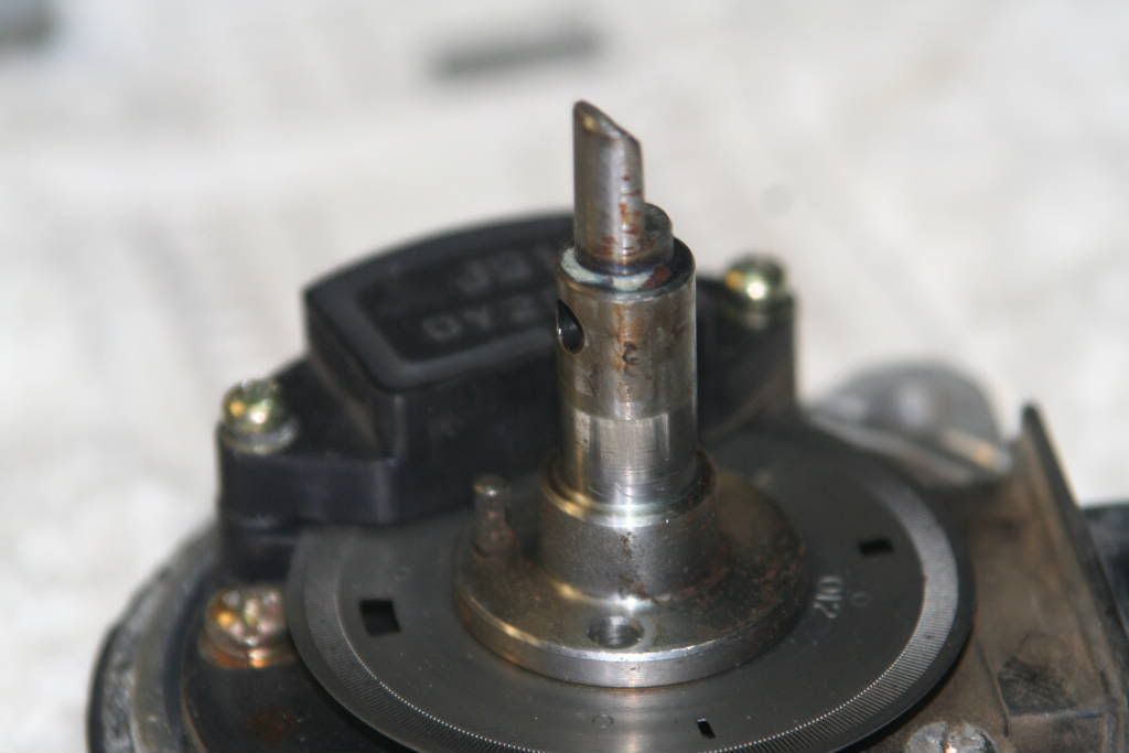
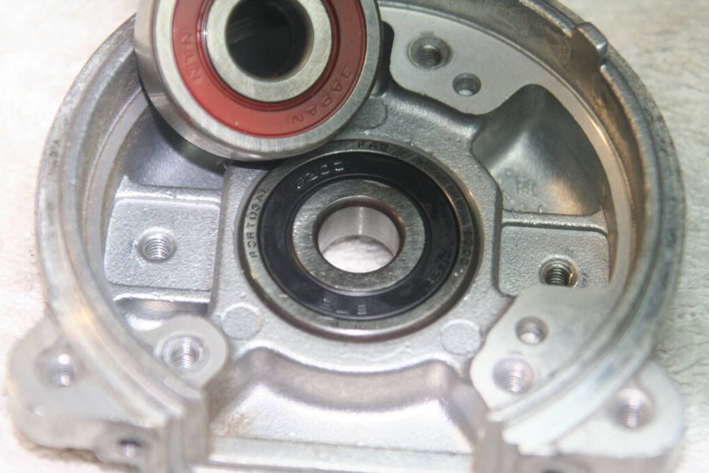
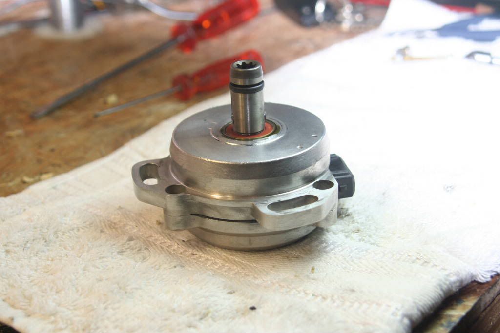
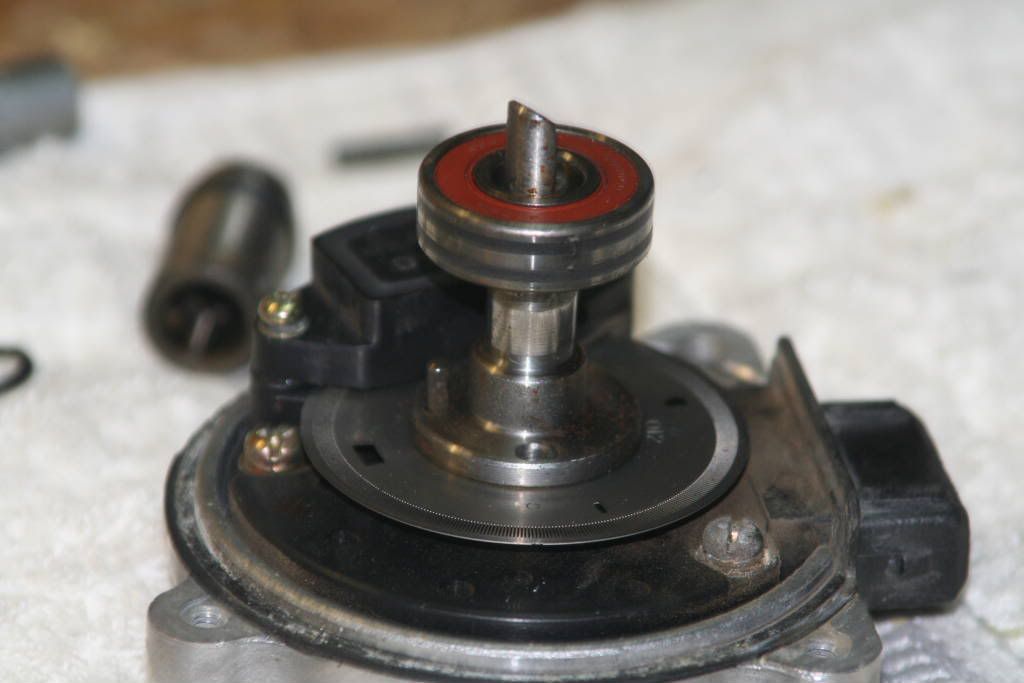
Your CAS housings should now be separated, and one piece should look like this.

Image

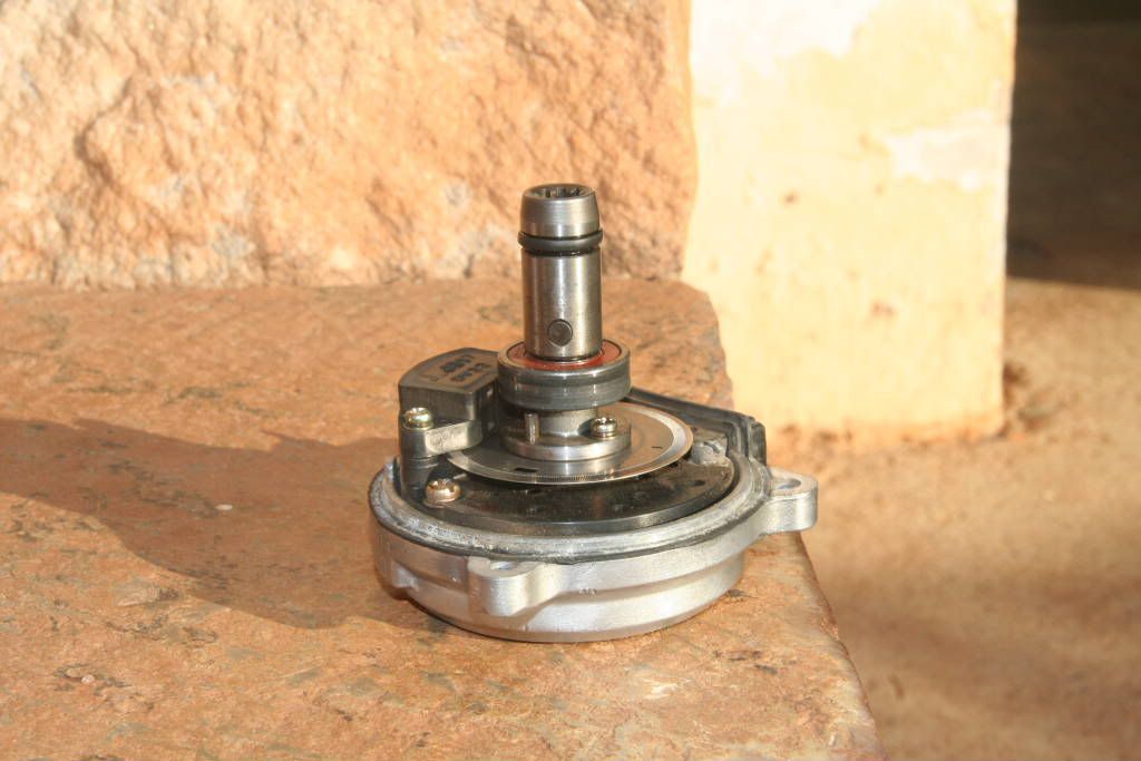
You can clearly see the different parts of the CAS.

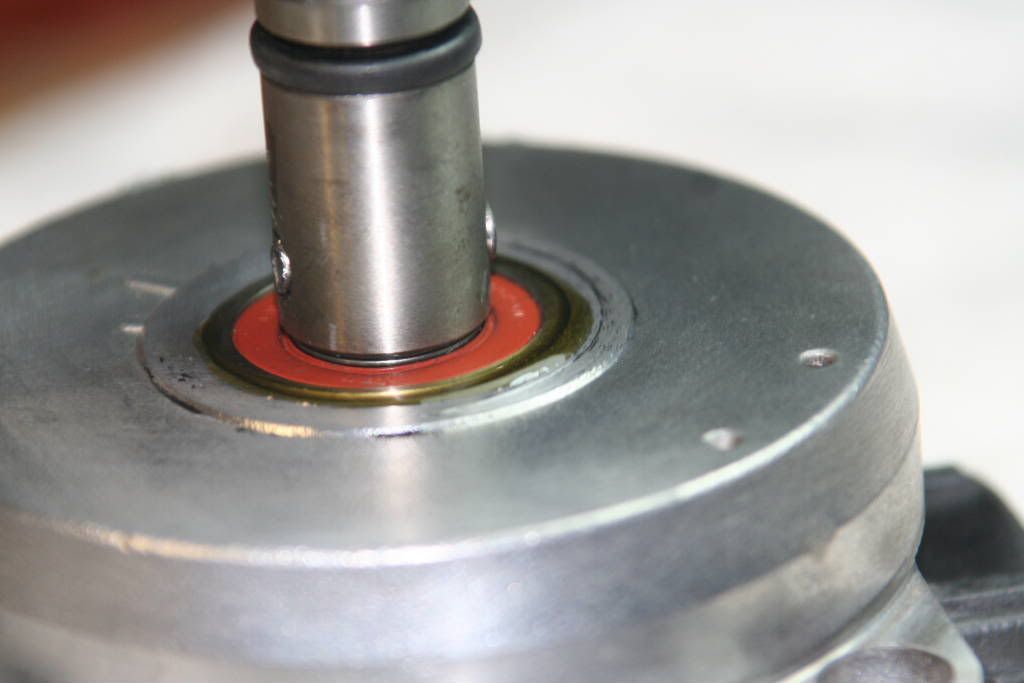
1 The splined shaft that is fitted over the half shaft and held in place with a pin. This shaft also should have a rubber O-ring near the top of it.

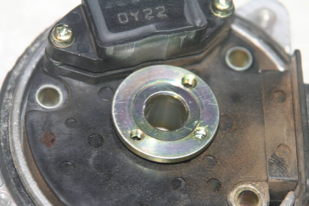
2 The smaller bearing, sized 6000.

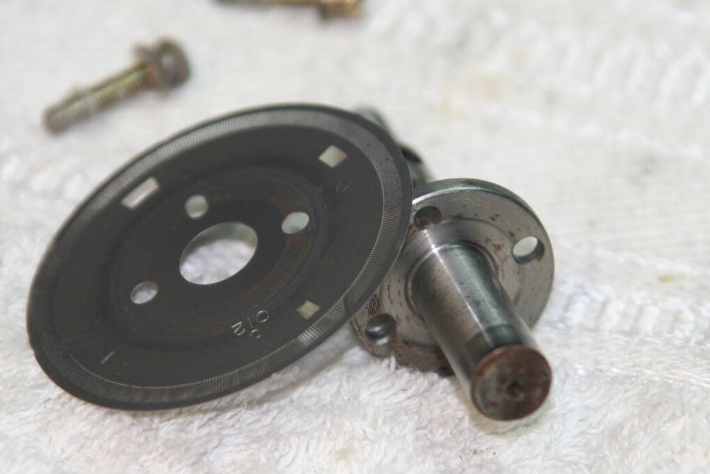
3 The chopper disc that is attached to the shaft.

4 The electronics component that covers the top and bottom of the chopper disc.

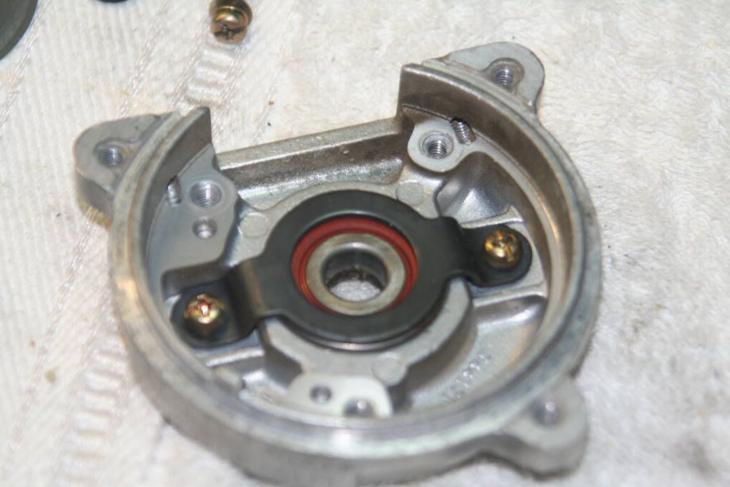
5 The seal around the edge of the housing that prevents most water and dirt from finding a way in. This seal is not water or dirt tight however, and it might be dirty in there!

Image

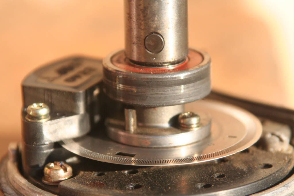
From this picture you can clearly see the scuff marks on the outer edge of the bearing. It is my assumption that the bearing was spinning inside the CAS housing. This is not supposed to happen, and may cause electrical interference, which may cause intermittent problems like I experienced.

Image

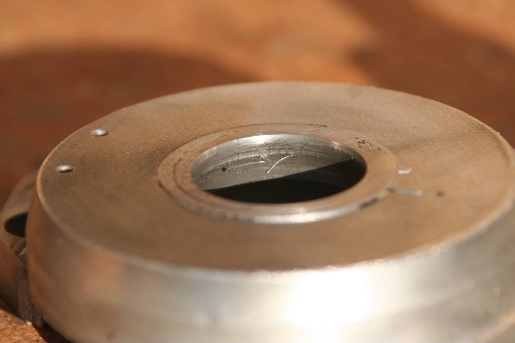
This picture of the housing that the small bearing was in also clearly shows evidence of metal rubbing on metal. In fact, the dirt on the inside of the housing was exactly like that produced when 1200 grit water paper, and water, is used to sandpaper aluminium.

Step three: A quick once over

Image

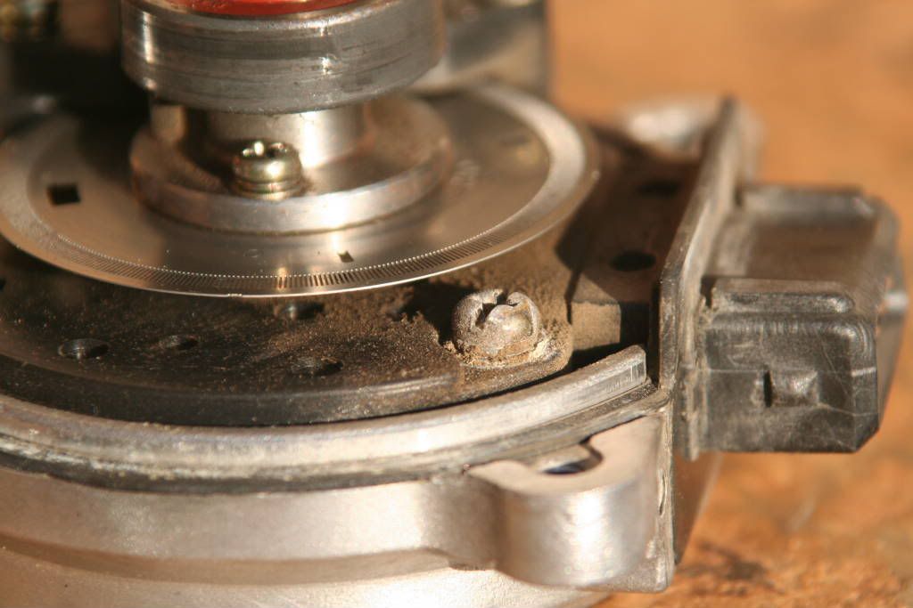
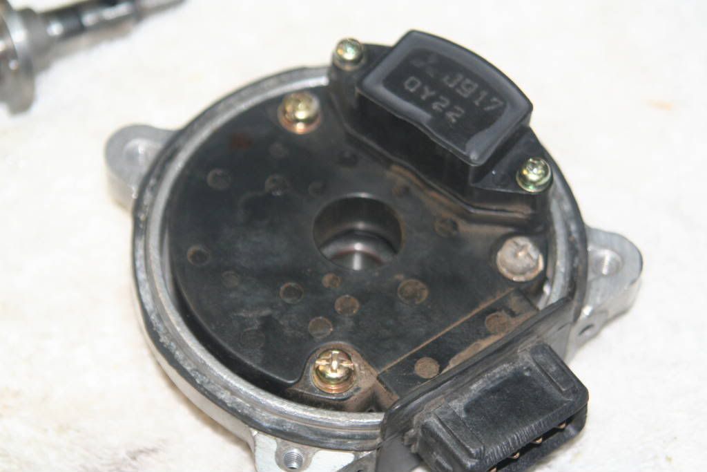
I added this step in so that people can quickly check out the state of their CAS’s. you should be looking for worn bearings, loose screws, a bent or damaged chopper wheel, dirt and dust build up, broken seals, etc. Basically check that everything is ok.

You can also see how much dust and dirt has built up inside my CAS. That just cannot be a good thing so I figured its best to clean it while I was busy taking it apart. Also, my bearings were badly worn, and I could tell because they would spin freely. The rest of the things mentioned though, were OK.

Image

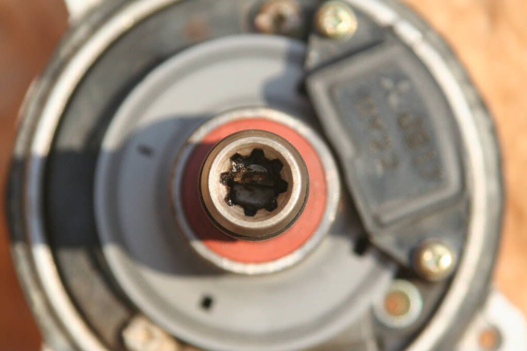
Another important check is on the condition of the splines and the locating pin in the CAS shaft. From this picture you can see that on this particular CAS they are fine. Just a bit of dirty grease in there, but that will be cleaned and replaced once the splined shaft is removed.

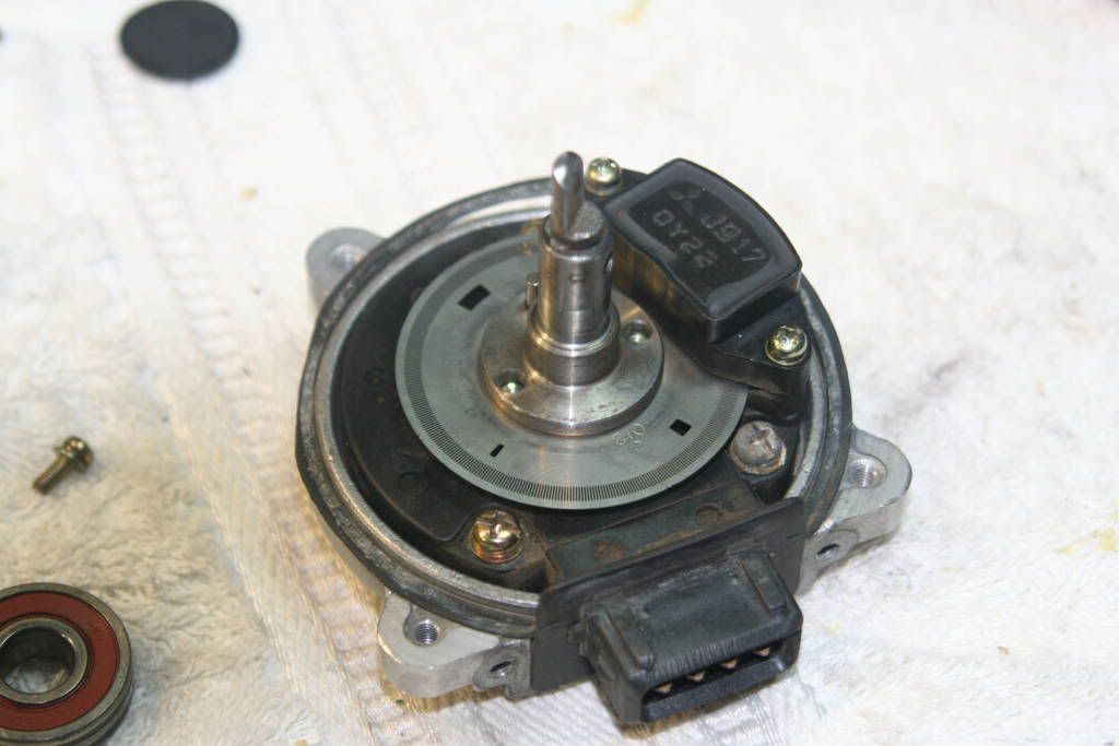
Step four: removing the splined shaft

Image

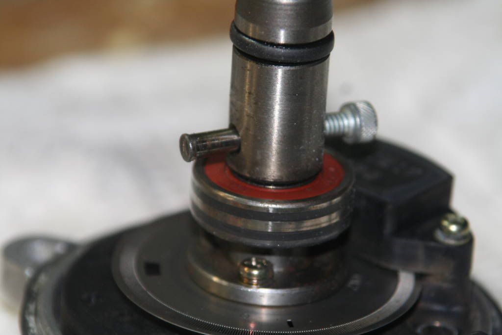
Remove the retaining pin that keeps the splined shaft in place. If you want to replace the bearing, this has to be done. But remember that one of the pins ends is flared slightly, so it can only be removed from one side. A press would be the ideal tool to do this step, but if that is not handy, there is a trick with a vice and a socket that works.

My CAS retaining pin was a real bastard to remove, so expect it to resist. You may think it’s not possible, but it is.

Once the pin has been removed the splined shaft will slide off. Be careful though, there is a rubber O-ring fitted between the splined shaft and the inner shaft. It can get damaged when you remove the splined shaft.

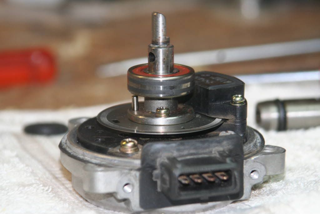
Step five: removing the smaller bearing

Image

I used a bearing puller to remove this bearing. I placed the center of the puller at the center of the half shaft. I then place the 3 arms of the puller around the bottom of the bearing and gave it a few turns, and it worked itself loose.

Once the bearing was out of the way, I also removed the screws that held the chopper place in place.

some more in the next post!
ReeceZ wrote:I'm sorry... I couldn't help it. Please no one wish any hateful shit on me, I own an SX already

veecee
AGENT SX!
Posts: 7353
Joined: Wed Nov 08, 2006 3:49 pm

Post by veecee »

Step six: removing the inner shaft

Image

You should now be left with something like the picture above.

The retaining pin that aligns the chopper disc can now also be removed with a gentle tug. If it does not want to budge, you may have to persuade it with a few light taps of a small hammer.

And now for the little trick!!!

You need to turn the CAS around, and remove the black plastic seal (the one that has a Mitsubishi sign on it). It can be pried out with a small flat screwdriver. Behind the round plastic cover you will see the inner piece of another bearing, and the other end of the shaft pressed into the middle of it.

You can now press, or gently tap, the shaft out of the bearing. This will release the whole shaft out of its housing, and you should be left with the parts illustrated in the next two pictures. Note that the chopper disc is installed with the stamped letters and number up!

Image

This is the shaft after it was pressed out of the bearing. The chopper wheel is there too, and you can see the stamped numbers on it. When you re-assemble the CAS, the numbers should be face up.

Be careful not to bend or damage the chopper wheel while removing it.

Step seven: removing the electronics

Image

Here you can see the bottom half of the chopper wheel retainer. The shaft simply slides into this piece when you are ready to reassemble the CAS.

Note also that I have now removed the three screws that hold the electronic module of the CAS in place. The electronics should now be simple to remove.

Be careful not to bend or damage the chopper wheel while removing it.

Step eight: removing the large bearing

Image

There is a retaining plate that holds the large rear bearing in place. Remove the two screws to remove the plate, and the bearing is easily removable by hand.

The bearing number is 6200, and should be easy to source from a bearing agent.


Step nine: replace large bearing

Image

The bearings can now be replaced, and the retaining plate can also be put back. Remember that the housing is made from aluminium and that the screws do not have to be extremely tight. If you are worried about them loosening over time, then please use a little loctite thread locker fluid.

Step ten: installing the electronic module.

Image

After I cleaned everything, I replace the electronics module. I made sure that the gasket was 100% ok, and I applied a little high heat RTV silicone sealant, in case! That’s because of the amount of dirt that I uncovered in there to start with.

The three screws are back in place now too, also not heavily tight – but just right!

Step eleven: installing the chopper wheel and shaft

Image

The lower half of the chopper wheel retainer needs to be installed first. You can then tap the pin into place, and place the chopper wheel onto it. Don’t forget that the numbers should be face up in this step.

You may have to loosen the two screws on the optical pickup unit to be able to get the chopper wheel over the locating pin if you follow this sequence. (but its the only way I’ve tried it!!!)

You can then tap the shaft into its place in the new larger bearing. But be very careful with the locating pin of the shaft – its important!

Step twelve: replace smaller bearing

Image

The new bearing can be tapped into place using a deep socket.

The splined shaft can also be installed at this stage, but remember to take care of the little O-ring. It can easily get damaged in this process.

Once that is assembled you are ready to place the housing back, and then you have a refurbished CAS.

Step thirteen: replacing the housing

Image

Because the new bearing was suspiciously close to being lose (just like the old bearing), I opted to use loctite thread locker fluid between the housing and the bearing. You can see it in this picture. This should prevent the bearing from spinning in the housing when it gets hot!!!

I then wiped off the excess and cleaned up the CAS, before installing it on my sx!!!

And its been going well since then on this CAS.

Thanks Vlade for the help again! And thanks always to Craig, ol’ buddy ol’ pal!!!
ReeceZ wrote:I'm sorry... I couldn't help it. Please no one wish any hateful shit on me, I own an SX already

User avatar
widowmaker
200SX Maniac
Posts: 3052
Joined: Wed Aug 02, 2006 9:50 am
Car: S13
Real Name: Walter
Location: im from another planet?
Contact:

Post by widowmaker »

wow, boldly going where no man has gone before...

interesting stuff - what made you look in there in the first place?

veecee
AGENT SX!
Posts: 7353
Joined: Wed Nov 08, 2006 3:49 pm

Post by veecee »

it was the last resort. if that didnt work, i think i probably would've burnt the damn CA18. and the SX knew that i reckon.

at that stage i didnt even care if murphy heard those sentiments!!!!
ReeceZ wrote:I'm sorry... I couldn't help it. Please no one wish any hateful shit on me, I own an SX already

User avatar
Toby
Club Founder
Posts: 1876
Joined: Tue Aug 01, 2006 10:44 am
Car: S13
Real Name: Toby Kurien
Location: Midrand
Contact:

Post by Toby »

Very nicely done, Veecee :-) Of course I was very nervous reading that, 'cos I was thinking that could be my CAS doing the modelling... hehehe :lol: :lol:
Red 200SX S13, 1992, stock. <a href="/phpBB3/viewtopic.php?t=332">Engine rebuilt (click)</a>.

veecee
AGENT SX!
Posts: 7353
Joined: Wed Nov 08, 2006 3:49 pm

Post by veecee »

Toby wrote:Very nicely done, Veecee :-) Of course I was very nervous reading that, 'cos I was thinking that could be my CAS doing the modelling... hehehe :lol: :lol:
nope toby, i wouldn't do that without your permission.

your CAS remains intact, and as of this morning at 9am, finds itself in the possession of a certain old man that prefers to cool things with chemicals!!!

thanks very much for letting me use it to troubleshoot my problem, and i hope it returns to you in better condition than it left!
ReeceZ wrote:I'm sorry... I couldn't help it. Please no one wish any hateful shit on me, I own an SX already

The Calibrator
0.4 Bar Boost
Posts: 498
Joined: Wed Nov 22, 2006 6:36 am
Car: S13

Post by The Calibrator »

the retaing pin is peened over. I f you drill the end for about 2mm you can drift the pin ouit easily away from the drilled end.
Makes it easy to put back in and I havnt had one come apart yet.

User avatar
widowmaker
200SX Maniac
Posts: 3052
Joined: Wed Aug 02, 2006 9:50 am
Car: S13
Real Name: Walter
Location: im from another planet?
Contact:

Post by widowmaker »

veecee wrote:finds itself in the possession of a certain old man that prefers to cool things with chemicals!!!
well, cool old man or not - don't you think hes getting a bit fat? (i hear he eats 8 times a day???) :wink:
ogaats hes online - gottago!

@ calibrator, do you use the same pin then? how do you make it stick?

veecee
AGENT SX!
Posts: 7353
Joined: Wed Nov 08, 2006 3:49 pm

Post by veecee »

The Calibrator wrote:the retaing pin is peened over. I f you drill the end for about 2mm you can drift the pin ouit easily away from the drilled end.
Makes it easy to put back in and I havnt had one come apart yet.
there is really no need for this if you just press it out from the correct side. and press it back in the same way it came out. that way you dont have to worry about it working itself loose.
ReeceZ wrote:I'm sorry... I couldn't help it. Please no one wish any hateful shit on me, I own an SX already

User avatar
Vlade
* - Club Pimp - *
Posts: 2775
Joined: Thu Oct 19, 2006 9:40 am
Car: Other
Real Name: Barend
Location: Auckland, New Zealand

Post by Vlade »

veecee wrote:
The Calibrator wrote:the retaing pin is peened over. I f you drill the end for about 2mm you can drift the pin ouit easily away from the drilled end.
Makes it easy to put back in and I havnt had one come apart yet.
there is really no need for this if you just press it out from the correct side. and press it back in the same way it came out. that way you don't have to worry about it working itself loose.
I don't have a press, even my vice didn't wan to do it, so drilling it was the only way I could get it going.
Hairdresser MX5

veecee
AGENT SX!
Posts: 7353
Joined: Wed Nov 08, 2006 3:49 pm

Post by veecee »

Vlade wrote:
veecee wrote:
The Calibrator wrote:the retaing pin is peened over. I f you drill the end for about 2mm you can drift the pin ouit easily away from the drilled end.
Makes it easy to put back in and I havnt had one come apart yet.
there is really no need for this if you just press it out from the correct side. and press it back in the same way it came out. that way you don't have to worry about it working itself loose.
I don't have a press, even my vice didn't wan to do it, so drilling it was the only way I could get it going.
i dont have a press either, but we got it right with a vice. eventually. it was very very tight in there! i reckon i would drill it though if i was trying to remove it without any help. it always helps to have a couple of extra hands in the mix!
ReeceZ wrote:I'm sorry... I couldn't help it. Please no one wish any hateful shit on me, I own an SX already

User avatar
Vlade
* - Club Pimp - *
Posts: 2775
Joined: Thu Oct 19, 2006 9:40 am
Car: Other
Real Name: Barend
Location: Auckland, New Zealand

Post by Vlade »

veecee wrote:i dont have a press either, but we got it right with a vice. eventually. it was very very tight in there! i reckon i would drill it though if i was trying to remove it without any help. it always helps to have a couple of extra hands in the mix!
Yeah our vice is a bit funny, you can't over tighten it or else it springs loose :wink:
Hairdresser MX5

Post Reply