Article #3: Rods and ends!!!

How-to's, project cars, and various other articles posted by club members

Moderators: P3g4sus, Daniel, rat, Draco, Riekert

Post Reply
veecee
AGENT SX!
Posts: 7353
Joined: Wed Nov 08, 2006 3:49 pm

Article #3: Rods and ends!!!

Post by veecee »

ok, so you all know i've had a little issue with bent tie rods.

i did some digging around, and it seems that the sentra/sabre from 92 onwards share exactly the same steering rack, and the wheel base only differs slightly (a few millimeters). this means that the parts are directly interchangeable, and can be found at any local parts store!!!

sentra/sabre tie rods = partquip TR-5398
sentra/sabre tie rod ends = partquip TR-5365.

here's HOW TO...

First some tech info:

1. TIE ROD COMPARISON

Dimension Nissan S13 OEM / Partquip # TR 5398
Rod Length 260mm / 270mm
General Diameter 11mm / 14mm
Smallest Diameter 11mm / 11mm
Length of Smallest Diameter 58mm / 14mm
Neck Diameter for Boot 12mm / 13mm
Rack End Insert M16 x 1.0 / M16 x 1.0
Rack End Insert Thread Length 21mm / 18mm

Image
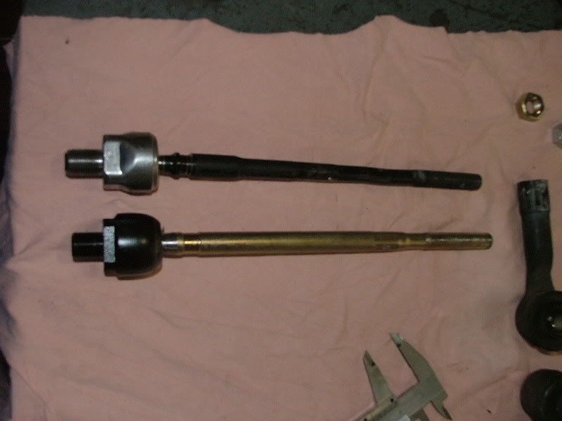
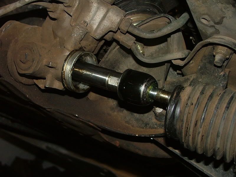
Picture 1. Nissan tie rod (black) versus Partquip tie rod (gold).

TIE ROD END COMPARISON

Dimension Nissan S13 OEM / Partquip # TR 5365
Neck Thickness 9mm / 16mm
Neck Width 18mm / 23mm
Thread Wall Thickness 5mm / 8mm

Image
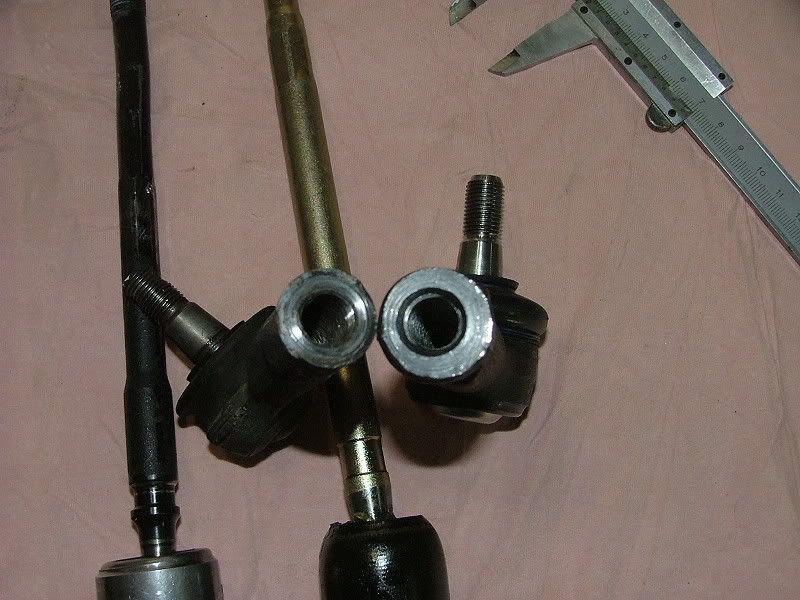
Picture 2. Nissan rods and ends (left) vs Partquip rods and ends (right)

Image
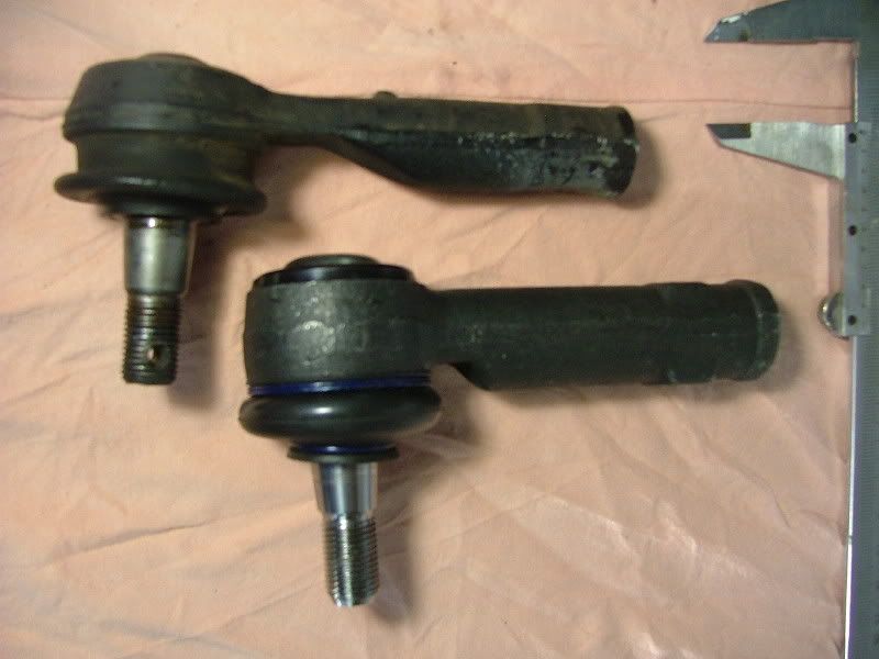
Picture 3. Rod End neck comparison. Nissan (top) vs partquip (bottom)

Image
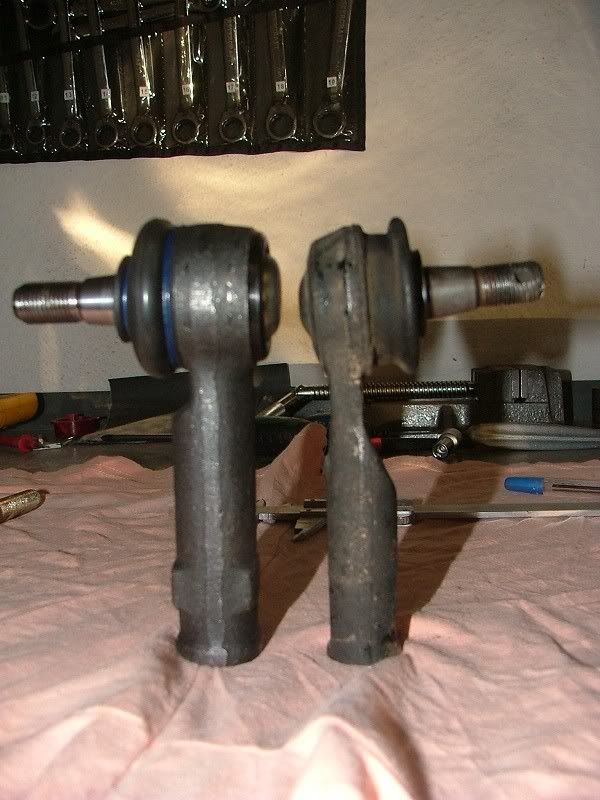
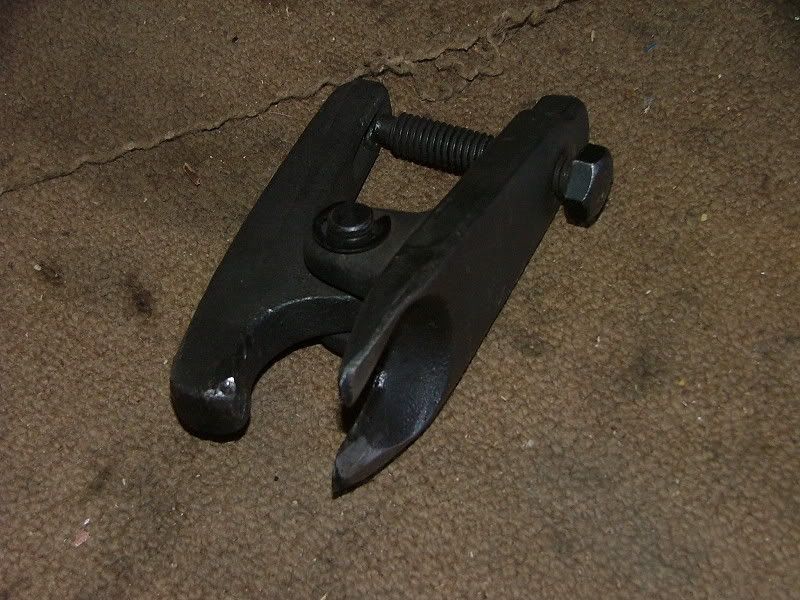
Picture 4. Rod End profile. Partquip (left) vs Nissan (right)

It is therefore clear that the all things being equal, the replacement parts distributed by Partquip SA, and available at most spares shops, are more than adequate to handle the original tasks set by the designers at Nissan. The parts supplied by Partquip, are used within a number of Nissan Vehicles including the Nissan Saber (1992 upwards), Nissan Sentra (1992 upwards), and Nissan Almera; all with Power Steering Racks.

The bonus is that these parts altogether cost only R236.85, which roughly translates into a 93% saving over expensive aftermarket drift parts!

I would go as far as to say that these locally available Tie Rods and Tie Rod Ends will be even better than OEM, especially for the abuse that they receive on the drift track. Although, this statement is yet to be tested on the track. Whether they will be better than the aftermarket rods and ends will not be discussed here, and should be subject to strict testing on a racetrack!

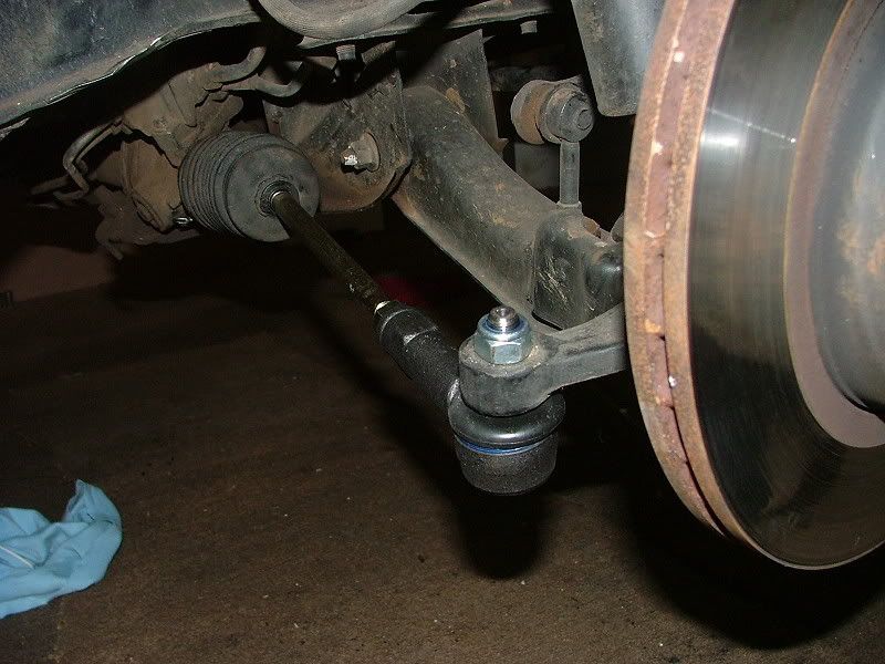
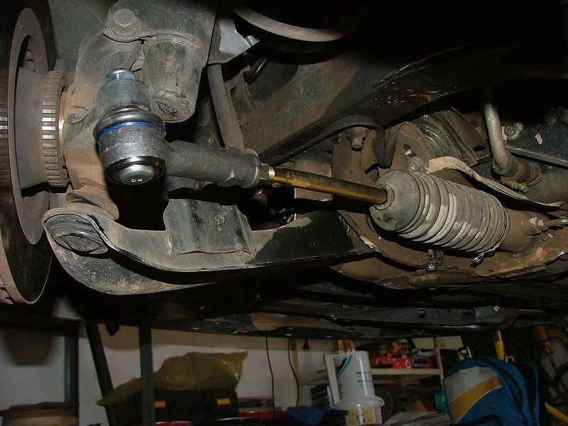
my next post will begin with the step by step guide to installing!
ReeceZ wrote:I'm sorry... I couldn't help it. Please no one wish any hateful shit on me, I own an SX already

veecee
AGENT SX!
Posts: 7353
Joined: Wed Nov 08, 2006 3:49 pm

Post by veecee »

Step 1: Remove the Tie Rod Boot.

Jack up the car and remove the front wheels. This gives you easier access to the steering system. Once the work area has been cleared of little things like wheels, and the car is hopefully on a set of jack stands, then you can begin by removing the twisted wire ring that holds the large end of the steering boot to the steering rack.

Image
Picture 5. Twisted wire ring on steering rack side (large side) of tie rod boot.

Pull the boot back to reveal the ball joint between the tie rod and the steering rack.

Image
Picture 6. Ball joint between steering rack and tie rod.

TIP – measure the visible length of the original tie rods. Once you have replaced the tie rods and set them to this measurement, you will be able to drive to a wheel alignment shop.

Step 2. Remove the Tie Rod

In picture 6 you can clearly see the ball joint on the inner side of the tie rod. This ball joint has four flat edges to facilitate removal with a size 30 spanner, or similar tool.

You will have to use a hammer and a screwdriver to bend the tabs of the retaining clip/plate back so that the tie rod inner ball joint can be unscrewed. The thread of the inner ball joint stud is very fine and therefore it might be a little tough to loosen.

You will also have to remove the tie rod from the tie rod end. This is easy once the locking nut on the tie rod is loosened.

Image
Picture 7. Tie Rod end. The Ball joint nut is visible on the left of the picture, and the tie rod locking nut on the right.

You should be able to remove the tie rod now.

Step 3: Remove the Tie Rod End.

Picture 7 clearly shows the tie rod end attached to the spindle and the tie rod. Your tie rod should already be removed, leaving your tie rod end attached to the spindle.

The Tie Rod End is attached to the spindle via a ball joint, and this has to be removed. Although it seems simple, this part can be tricky and use of the illustrated special tool will greatly ease the process along.

Image
Picture 8. Special tool for cracking ball joints loose.

You should remove the rod end ball joint nut with a size 19 spanner or ratchet.

You will then insert the special tool with the forked end between the tie rod boot and the spindle. The special tool’s slightly mushroomed end should make contact with the top of the rod end’s bolt.

You then need to tighten the special tool, as this applies downward pressure to the top of the ball joint bolt.

Because ball joints are tapered they have a very tight fit, and may need some convincing! Lightly tap the top of the mushroom end of the special tool and this should see the ball joint cracking loose!

You should now have removed the tie rod end.

Step 4: Replace the Tie Rod.

Your steering rack should now look like the picture below.

Image
Picture 9. Bare Steering rack end.

Put the tie rod boot onto the new tie rod.
Insert the new retaining clip/plate and screw in the new tie rod.
Using a flat screwdriver and a hammer, knock the edges of the retaining clip/plate onto the flat edges of the tie rod ball joint.

Image
Picture 10. New tie rod installed.

Replace the boot and twist the ring closed to hold it in place.
Repeat this step for both sides of the steering rack.

Image
Picture 11. Tie Rod replaced.

Step 5: Replace the Tie Rod End.

Screw the new Tie Rod End onto the new Tie Rod.

Image
Picture 12. New Tie Rod screwed onto new Tie Rod.

Place the new Tie Rod End Ball Joint into its place on the spindle, and tighten the Ball joint nut.

Image
Picture 13. Tie Rod End Ball Joint located securely on the wheel spindle.

TIP – set the new tie rods to the length measured in step 1. This will ensure that your wheels are roughly pointing in the same direction, and have minimal toe in or toe out, so that you will be able to drive to a wheel alignment shop.

Tighten the tie rod end locking nut.

Make sure that all loosened nuts and bolts have been retightened to factory spec’s.

Image
Picture 14. New Tie Rods and Ends installed.

Put the wheels back on.

Lower the car off of the jacks.

Drive to your local alignment shop.
ReeceZ wrote:I'm sorry... I couldn't help it. Please no one wish any hateful shit on me, I own an SX already

User avatar
Stephen Swanepoel
0.5 Bar Boost
Posts: 584
Joined: Sun May 13, 2007 7:02 pm
Car: S13

Post by Stephen Swanepoel »

Nice thats what you call reasearch. 8)

veecee
AGENT SX!
Posts: 7353
Joined: Wed Nov 08, 2006 3:49 pm

Post by veecee »

thanks! i try!
ReeceZ wrote:I'm sorry... I couldn't help it. Please no one wish any hateful shit on me, I own an SX already

Ero_sennin
SX Forumholic
Posts: 1718
Joined: Tue Aug 01, 2006 4:00 pm
Car: S13
Engine: SR
Location: Will always be called Pretoria
Contact:

Post by Ero_sennin »

great info! If I understand this those part seem thicker so should be stronger! test them out and let us know!!!!!!
SONY Xplod inside
SR20DET Powered Red RS13
Image

veecee
AGENT SX!
Posts: 7353
Joined: Wed Nov 08, 2006 3:49 pm

Post by veecee »

oh yes, i forgot that i did test them out.

i nailed them on the track last night, and they held up!!!

i did put my alignment out slightly though, but the arms look straight, so i think that maybe the operator didnt tighten them properly.

i will check again when i get back into my garage this weekend!
ReeceZ wrote:I'm sorry... I couldn't help it. Please no one wish any hateful shit on me, I own an SX already

User avatar
Vlade
* - Club Pimp - *
Posts: 2775
Joined: Thu Oct 19, 2006 9:40 am
Car: Other
Real Name: Barend
Location: Auckland, New Zealand

Post by Vlade »

If I could hand out gold stars and and stick it on your forehead I would... Brilliant writeup VeeCee!
Hairdresser MX5

User avatar
Phinx
0.7 Bar Boost
Posts: 720
Joined: Fri Oct 20, 2006 12:30 pm
Car: S13
Location: Pretoria

Post by Phinx »

Thanks Veecee...

I will get some next week.
i did some digging around, and it seems that the sentra/sabre from 92 onwards share exactly the same steering rack, and the wheel base only differs slightly (a few millimeters). this means that the parts are directly interchangeable, and can be found at any local parts store!!!
I wonder if this means the 200sti strut brace will fit?
Damn maybe I should buy one and see ....
A.K.A - Wonderboy
~~~~~~~~~~~~~~~~~~~~~~~~~~~~~
1993 Nissan 200 SX
148 Kw - 250 NM @ 0.55 bar. 1.8T ATW
~~~~~~~~~~~~~~~~~~~~~~~~~~~~~
1989 Toyota Corrola
63kw - 117nm 1.3- N/A
18.2 @118,4 Km - Rainbow Raceway
~~~~~~~~~~~~~~~~~~~~~~~~~~~~~

Ero_sennin
SX Forumholic
Posts: 1718
Joined: Tue Aug 01, 2006 4:00 pm
Car: S13
Engine: SR
Location: Will always be called Pretoria
Contact:

Post by Ero_sennin »

Great!! the more parts+numbers we can get the better
SONY Xplod inside
SR20DET Powered Red RS13
Image

veecee
AGENT SX!
Posts: 7353
Joined: Wed Nov 08, 2006 3:49 pm

Post by veecee »

Phinx wrote:Thanks Veecee...

I will get some next week.
i did some digging around, and it seems that the sentra/sabre from 92 onwards share exactly the same steering rack, and the wheel base only differs slightly (a few millimeters). this means that the parts are directly interchangeable, and can be found at any local parts store!!!
I wonder if this means the 200sti strut brace will fit?
Damn maybe I should buy one and see ....
no problem - i'm also wondering if it will fit.

i would be sceptical of the fitment of the mounting brackets, but the strut itself might be the same length.

perhaps i should be more detailed in what i meant by "and the wheel base only differs slightly (a few millimeters)". this was an assumption, based on the fact that the steering rack is the same, as are the tie rods, and the tie rod ends. it may differ drastically from the tie rod end mounting point on the spindle outward though - so this could end up being a grossly misinformed assumption!!!
ReeceZ wrote:I'm sorry... I couldn't help it. Please no one wish any hateful shit on me, I own an SX already

User avatar
ChemCool
SX Forumholic
Posts: 2197
Joined: Tue Aug 01, 2006 11:59 am
Car: S13
Location: Centurion
Contact:

Post by ChemCool »

Brilliant and thank you VC [smilie=200sx_rockon.gif]
Now that we know this, would you say there is regular maintenance needed on these rods? Like checking grease? Must be honest, I did not check up in the manual. Specifically for our sx owners only dreaming of drifting :oops:
COOLER, FASTER, LIGHTER
www.wappage.mobi AGENTS NEEDED URGENTLY!

Image

Ero_sennin
SX Forumholic
Posts: 1718
Joined: Tue Aug 01, 2006 4:00 pm
Car: S13
Engine: SR
Location: Will always be called Pretoria
Contact:

Post by Ero_sennin »

"Hi there, do you have one of those for a 200sx"

"Is that a sentra?"

:wink:

Maybe they not always too far off, hehe
SONY Xplod inside
SR20DET Powered Red RS13
Image

veecee
AGENT SX!
Posts: 7353
Joined: Wed Nov 08, 2006 3:49 pm

Post by veecee »

ChemCool wrote:Brilliant and thank you VC [smilie=200sx_rockon.gif]
Now that we know this, would you say there is regular maintenance needed on these rods? Like checking grease? Must be honest, I did not check up in the manual. Specifically for our sx owners only dreaming of drifting :oops:
hey chemcool - i dont reckon that you need to replace the rods or the grease regularly. i noticed though that both my tie rod ball (inner end) and tie rod end ball joint (outer end) were worn.

but all that means is that the joints were easy to move, they weren't broken. they are supposed to be quite toight - you know difficult for us laaitjies to move by da hand...

but on da udda hend derren, i've heard of people getting the "phantom knocking sound" from the front chassis. its more of a feeling than an audible sound, and its often attributed to both worn tie rod ends, and excessively lowered cars (like mine) that do not have any form of bump steer adjustment or compensation.

see!!!???!!!
ReeceZ wrote:I'm sorry... I couldn't help it. Please no one wish any hateful shit on me, I own an SX already

User avatar
Toby
Club Founder
Posts: 1876
Joined: Tue Aug 01, 2006 10:44 am
Car: S13
Real Name: Toby Kurien
Location: Midrand
Contact:

Post by Toby »

Nice write-up VC! Also, for those who have slightly worn tie-rod ends, there is a simple, quick and cheap solution. A lot of mobile tie-rod repairers can come to your place and fix it in about half an hour. They drill a hole into the cup, inject plastic in molten form, then seal the hole. Did this with my previous Honda and it held up for years afterwards with no problems. Drifters might want a more sturdy fix tho...
Red 200SX S13, 1992, stock. <a href="/phpBB3/viewtopic.php?t=332">Engine rebuilt (click)</a>.

Post Reply